It became very clear very quickly that I would need some way of testing the T4 units that were at the the heart of the sound of the LA-2A. Every LA-2A that I had worked on had different compression characteristics and the T4 units were obviously a major contributor to this effect. I knew I had to have some way to reliably and accurately measure the differences between T4 units if I was ever going to successfully make my own units. I searched the Web, posted on the usual newsgroups and asked several "old timers" I knew for any information about how Teletronix tested their units, but the only thing I could find out is that they had built a custom tester that had a pushbutton and an analog meter on it.
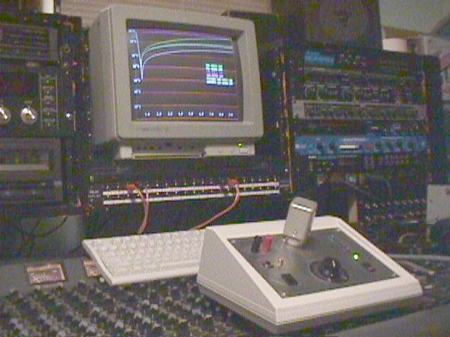
Based on that information there was no way I could build a reliable test fixture so I had design one with only my wits and cunning to get me there. The test fixture I needed had to be (1) accurate, (2) repeatable and (3) versatile enough to test all meaningful response characteristics of the vintage T4 units in the LA-2As I was repairing, as well as the T4 units I built from scratch. What I came up with was a computer-controlled tester using modern circuitry and data acquisition techniques that was much more accurate and versatile than any other T4 tester I've ever heard of. This unit incorporates a sine wave generator, a high voltage drive circuit for the electroluminescent (EL) panel and a precision analog-to-digital converter circuit to measure the photocell response. Both the frequency and amplitude of the signal driving the EL panel is variable via computer control. The frequency can be varied from just a few hertz to over 30 kilohertz. The amplitude can be varied from 1 volt to over 120 volts. This setup gives me more than enough flexibility to thoroughly test any T4 unit that comes through the door.
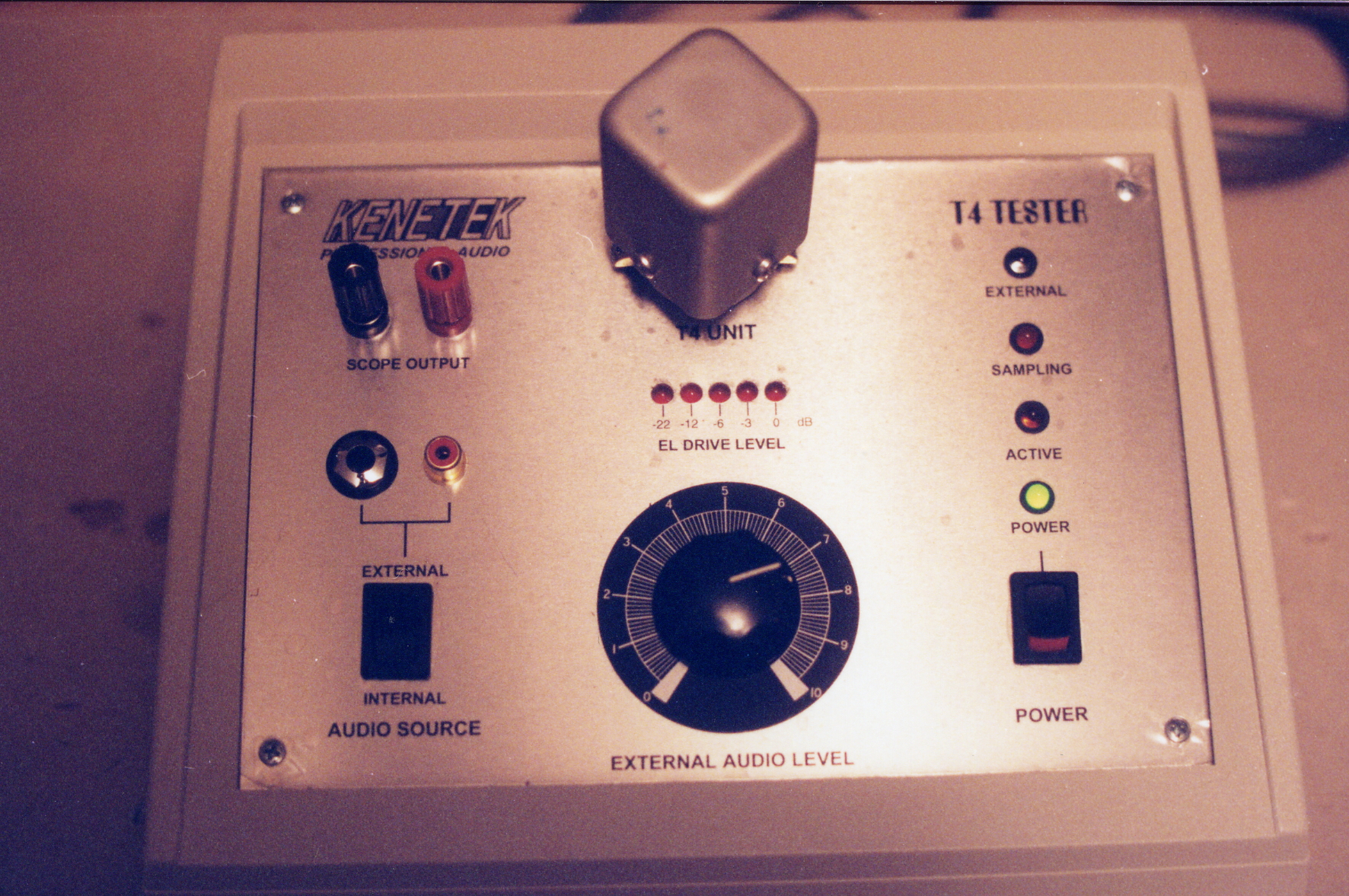
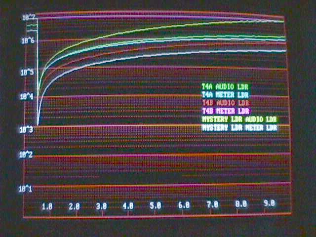
Since the frequency and amplitude of the test signals are controlled by the computer I was able to design several different tests, and have confidence that the measurements would allow apples-to-apples comparison between different T4 units. I eventually came up with two simple tests that reliably measured the compression characteristics of a T4 unit. The first test is an impulse test. This test applies a 1 kHz, 100 volt sine wave to the T4's EL panel for a duration of 250 milliseconds and measures the response of the photocell for 10 seconds after that. The second test test dynamic range. This test applies a 1 kHz signal whose voltage was varied from 20 volts up to 100 volts, as the resistance of the photocell is measured. The dynamic range test easily reveals when an EL panel had exceeded its useful life and needs replacing. This test also revealed dramatic differences between the EL panel used in the LA-2A and LA-3 and LEDs as used in the LA-4 and LA-5. EL panels have a much wider dynamic range than LEDs, and this leads to much smoother gain reduction characteristics and a wider useful range of compression.
The tests I wrote allow for up to six units to be compared on the same screen. The data can also be saved and imported into a spreadsheet program such as Microsoft Excel for more accurate analysis. Here is a screenshot of a typical test run:
I designed and built this unit in late 1997. I took me over a month of non-stop work to get the hardware designed and assembled and the software to a usable state. The software has gone through many revisions since then and now this tester is one of the projects I'm most proud of. It has proven invaluable in my pursuits of the ultimate electro-optical compressor/limiting amplifier.